

Specific local weaknesses such as the use of low-strength concrete, plain round bars, improper detailing in RC components, and unaudited construction adversely affect the seismic response of structures in existing RC building inventory [1]. Due to time, cost, and application constraints, demolition and re-construction of all these vulnerable structures is not feasible. As a result, upgrading processes are critical for improving the structural behavior of deficient structures and reducing the seismic risk of urban settlements [2]. Traditionally, upgrading procedures have relied on conventional methods [3]. One common approach involves employing local strengthening techniques to enhance the load-bearing capacity of specific structural elements [4, 5]. Alternatively, implementing supplementary support systems, structural walls, or other advanced mechanisms are some of the approaches to enhance the overall performance of structures [6, 7].
In recent years, the concept of performance-based seismic design and assessment has gained attraction, subsequently being incorporated into seismic design codes. Beyond ensuring life safety, these codes increasingly emphasize limited structural damage performance criteria even under severe earthquakes, aiming to maintain building functionality while minimizing imposed and residual drifts. As a result, earthquake engineering studies focusing on smart materials have increasingly addressed this growing emphasis on improved structural performance particularly through systems capable of providing self-centering behavior under cyclic loading. Among the various smart materials, SMAs stand out for their remarkable properties, including superelasticity (SE) and shape memory effect (SME). The inherent attributes of SMAs, including the ability to “remember” their original shape and geometry upon being deformed as a result of solid-to-solid phase transformations, allow them to return to their original shapes with negligible residual deformations after the load removal [8, 9].
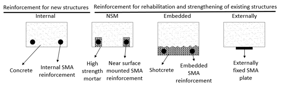
Numerous studies have demonstrated the effectiveness of SMAs in improving the seismic behavior of structures [2, 10]. SMAs have been used as an alternative to conventional materials for seismic retrofitting applications over the past two decades. They can be also used for retrofitting RC components through various techniques such as internal reinforcement in RC structural members, near-surface mounted (NSM) reinforcement, embedded reinforcement in shotcrete layer, and externally anchored reinforcement [11]. Superelastic Nickel-Titanium (Ni-Ti) and Copper-based SMA have previously been employed as internal reinforcements in beams [12, 13], columns [14], and BCJs [15, 16].
SMAs also show promise as NSM reinforcements in existing RC structures, particularly in enhancing flexural strength while minimizing post-inelastic displacements due to re-centering capacity. In this process, grooves are first cut in the concrete cover, followed by the implantation of SMA rebars in the grooves, which are subsequently filled with epoxy or cement mortar. Notable studies have highlighted the effectiveness of this approach in strengthening RC beams [17]. This technique has proven effective in increasing flexural strength, facilitating crack closure, and reducing residual displacements [11]. Several other studies have also explored the use of SMAs in structural applications beyond internal reinforcement. Ferraioli et al. [18] demonstrated the benefits of SMA-based self-centering braces in RC buildings. Alternative self-centering brace systems, such PT-SCYBS (post-tensioned self-centering yielding brace systems), have exhibited greater success in reducing residual drifts and maintenance expenses when utilized in steel or RC frames [19]. In addition, SMA–ECC jacketing has been shown to improve both load-bearing capacity and re-centering performance of deficient RC frames [20]. Furthermore, innovative SMA-based confinement and composite reinforcement strategies have been proposed to enhance sustainability and reduce residual drifts in RC structures [21]. However, these approaches generally involve global or sectional strengthening rather than targeted intervention at plastic hinge regions.
In addition to these general applications, several recent studies have offered deeper experimental and numerical insights into SMA-based structural systems. Abraik and Asteetah [22] introduced a novel slotted RC wall reinforced with SMA bars, showing superior seismic performance and self-centering ability in comparison to conventional designs. Meanwhile, Cui et al. [23] validated the axial capacity and confinement efficiency of UHPC tubular columns reinforced with self-prestressed Fe-SMA spirals, offering a durable, cost-effective solution for infrastructure under extreme loads.
Based on the conducted literature survey, it is noted that although SMA bars have been utilized to retrofit RC components, no systematic optimization study based on validated numerical models has been reported in the literature to determine the minimum effective configuration of SMA rebars in RC components. A validated numerical study that integrates optimization strategies with SMA bars is, therefore, needed. Indeed, various approaches have been proposed in the literature for modeling substandard RC components, with the lattice modeling approach being adopted in this study. The performance of the lattice modeling technique is assessed based on its ability to accurately replicate the response of various RC components [24, 25, 26]. For this purpose, a numerical study was combined with optimization strategy to investigate the effectiveness of retrofitting technique using various SMA rebar configurations in the structural members of a sub-standard RC frame. The selected RC frame exhibits strong beam–weak column behavior and contains deficient BCJs. Besides, it is constructed from low-strength concrete and non-seismic transverse reinforcement details. As a result, structural damage is predominantly localized at the column ends and BCJs of the tested frame.
SMA bars are currently more expensive than traditional steel reinforcement bars. However, because of the ability of SMA materials to revert to their original shape, they have the potential to enhance the seismic performance of the structural systems if utilized effectively [27]. Therefore, it is important to determine an optimum quantity of SMA rebars for retrofitting. To address such an issue, a study was conducted within the scope of this research. A ½ scale 3-story 3-span substandard RC frame, which was tested in the laboratory conditions using the pseudo-dynamic testing procedure, was modeled in the OpenSees [28] platform with the lattice modeling technique. Nonlinear time history analyses were then conducted on both the retrofitted and reference RC frames under the ground motion recordings applied during the tests. Then, the SMA rebar layout was optimized to find the most efficient sections.
The originality of this study lies in identifying the optimum configuration of SMA rebars to achieve an improved seismic response of the tested RC frame. Specifically, Ni-Ti and Cu-Al-Mn SMA rebars were used in different configurations only in the column sections of the plastic hinge regions in the first story. This approach aimed to minimize residual drifts while utilizing the least quantity of SMA rebars possible.
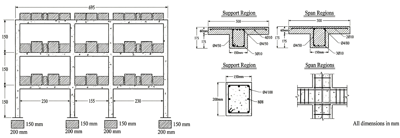
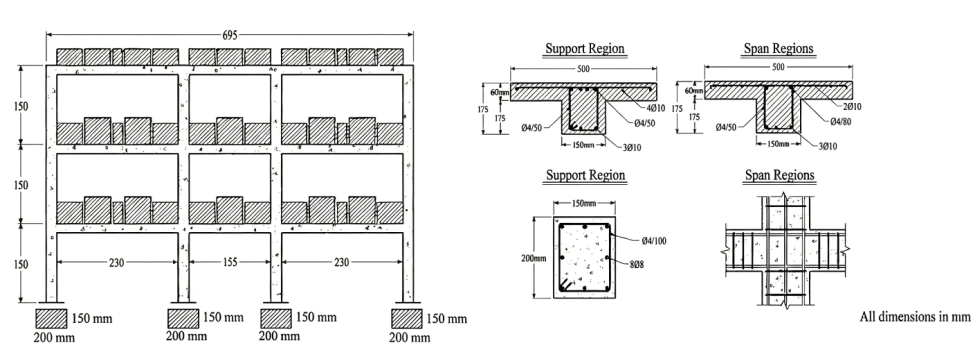
The lattice modeling approach was first validated using the experimental results of pseudo-dynamic testing performed by Mutlu [29] on an RC frame named SP3. The nonlinear time history analyses were carried out using the OpenSees program [28]. The test specimen represents a gravity-designed reinforced concrete frame incorporating non-ductile detailing, such as plain round reinforcement and low-strength concrete, which are characteristic of deficiencies observed in the Turkish building inventory. Table 1 and Figure 1 show the major features of the SP3 specimen, including the reinforcing details. The geometric details and the cross-section dimensions are shown in Figure 1. The cross-sections of all columns are oriented such that they work in their strong axes under the in-plane loading direction of the test frame. Plain rebars were used in column and beam sections having diameters of 8 mm and 10 mm, respectively. The yield strength of steel rebars with diameters of 8 mm and 10 mm were 320 MPa and 355 MPa, respectively. The strain limits adopted for the reinforcing steel are defined in accordance with the TBEC (2018) [30]. The onset of strain hardening is assumed to occur at a strain level of 0.008, whereas the ultimate strain capacity is taken as 0.08. The elastic modulus of the reinforcing steel is approximated as 200 GPa. The concrete used in the specimen is characterized by a low compressive strength, with an average value of 11.9 MPa. Axial load ratios applied at the ground-story columns are determined as 0.23A\({}_{c}\)f\({}_{c\ }\)for interior columns and 0.13A\({}_{c}\)f\({}_{c}\) for exterior columns, reflecting the gravity loads imposed by the additional masses illustrated in Figure 1. Further details about the specimen can be found in Sucuoglu et al. [31].
| Property | Value | |
|---|---|---|
| f\({}_{c}\) (MPa) | 11.9 | |
| f\({}_{y}\) (MPa) | 320 | |
| Type of longitudinal reinforcement | Plain | |
| Beam cross-section (mm) | 175 x 150 | |
| Column cross-section (mm) | 200 x 150 | |
| Beam longitudinal reinforcement ratio (%) | Support region | Span region |
| 1.8 | 1.1 | |
| Column longitudinal reinforcement ratio | 2% | |
| Transverse reinforcement in BCJ | N.A. | |
| Spacing of transverse reinforcement in column (mm) | Ø4/100 | |
| Spacing of transverse reinforcement in beam (mm) | Support region | Span region |
| Ø4/50 | Ø4/80 | |
| Column axial load ratio, N\({}_{d}\)/f\({}_{c}\)A\({}_{c}\) | Inner columns | Outer columns |
| 0.23 | 0.13 | |
| Application of displacement | At the floor level | |
| Loading type | Pseudo-Dynamic | |
| Failure mode | Damages at the member ends and BCJs | |
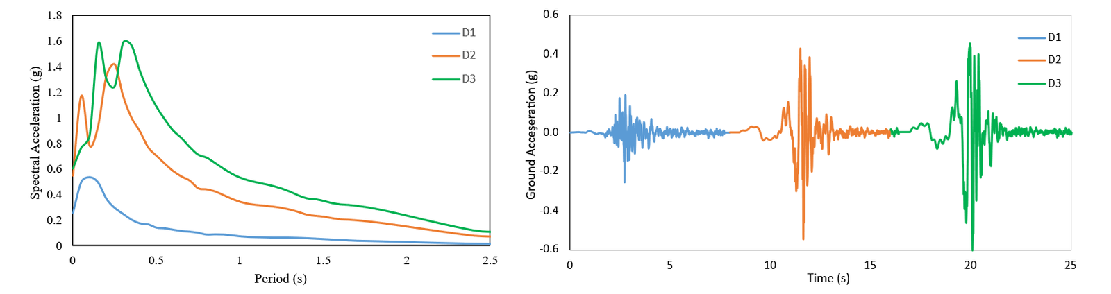
The earthquake input records adopted for the continuous pseudo-dynamic tests are summarized in Table 2. These records are selected to be compatible with the site-specific design response spectrum and to represent different soil conditions associated with varying exceedance probabilities. A total of three acceleration time histories, designated as D1, D2, and D3, are applied during the experimental program [31].
Figure 2 illustrates the applied acceleration time histories together with their loading sequence and the corresponding response spectra. xperimental observations indicate that the damage response of the reference frame is governed mainly by deformation and deterioration localized at the column ends and beam–column joint regions. Damage at the column ends is dominated by flexural action, leading to concrete crushing and extensive cracking, while shear-induced cracking is observed within the beam–column joint panel zones [29].
| Earthquake | Exceedance Probability in 50 Years | Soil Type | PGA (g) |
|---|---|---|---|
| D1 | 50 % | Rock | 0.254 |
| D2 | 10 % | Rock | 0.545 |
| D3 | 10 % | Soft | 0.604 |
A numerical model of the test frame is developed in the OpenSees platform [28] to reproduce the experimentally obtained results. When considering factors such as computational effort, capabilities, and analysis time, various nonlinear modeling techniques are available in the literature, ranging from lumped-parameter models to detailed finite-element models. Among these options, the lattice modeling technique, combined with fiber-based distributed plasticity modeling, is considered to be a suitable choice for the selected test frame [25]. In the lattice modeling technique, concrete, reinforcing steel, and bar slip elements of RC BCJs, as well as some portions of beam and column end sections, are represented as truss elements with uniaxial material characteristics. Accurate modeling of the test frame with the lattice modelling technique is accomplished with minimal computing effort compared to more sophisticated modelling approaches such as finite element modelling. The lattice structure is constructed using diagonal, vertical, and horizontal elements that represent tension/compression strut force transfer mechanisms. Bond–slip interaction between reinforcing bars and surrounding concrete is simulated through zero-length spring elements connected to the concrete and steel components. The constitutive response of concrete truss members is governed by a nonlinear stress–strain relationship, whereas the steel truss members are characterized by a uniaxial constitutive model representing the behavior of reinforcing steel.
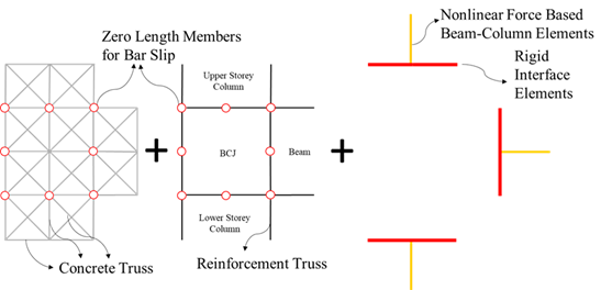
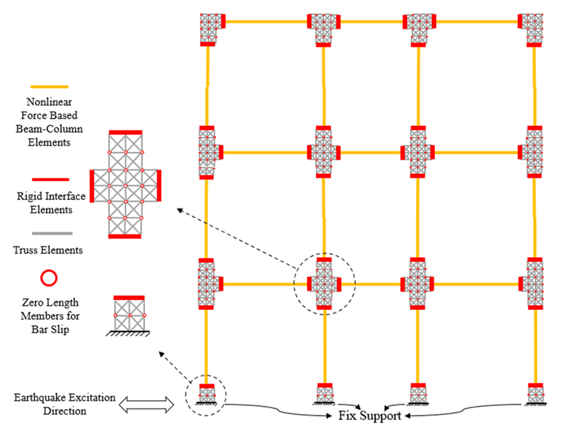
The overall layout of the lattice model, including RC BCJs and portions of beam and column end zones, is shown in Figure 3. Concrete, reinforcement, bar slip, and rigid elements constitute the model. A cell structure is formed by vertical and horizontal concrete elements, and the mesh size of the model is determined by the dimensions of each cell containing diagonal concrete struts. These diagonal elements primarily provide main shear resistance, while vertical and horizontal concrete elements, along with reinforcing steel, contribute to flexural resistance. Nonlinear zero-length springs linking the concrete and steel parts depict the bar slip behavior.
The cross-sectional properties assigned to the concrete truss elements are illustrated in Figure 4. For the vertical and horizontal concrete members, the cross-sectional area is computed by multiplying the out-of-plane thickness by half of the tributary width (b/2). In contrast, the effective width of the diagonal concrete members is evaluated using Eq. (1), as proposed by Xing [32]. Accordingly, the cross-sectional area of each diagonal member is obtained from the product of the out-of-plane thickness and half of the corresponding effective width. The use of half of the tributary width for all concrete truss elements accounts for overlapping load-transfer regions within the lattice framework [33, 34]. \[\label{GrindEQ__1_} b_{{eff}}{=}\frac{{a}{\ }{x}{\ }{b}}{\sqrt{{{a}}^{{2}}{+}{{b}}^{{2}}}}. \tag{1}\]
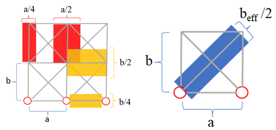
The cross-sectional areas assigned to the reinforcement truss elements are determined according to the total amount of longitudinal steel, with the truss members distributed along the perimeter of the section. Interaction between the beam–column joint and the adjoining beam or column segments is represented using a rigid beam–column element. This modeling strategy enforces the plane-section assumption, maintaining sectional compatibility during deformation. The nodes connecting the truss elements to the rigid beam–column components are linked through EqualDof constraints in the translational degrees of freedom along the x and y directions, thereby preserving kinematic consistency within the model.
The ConcretewBeta material model available in OpenSees [28] was employed to simulate the compressive and tensile behavior of concrete. The concrete characteristics of the trusses are defined using the constitutive model by Lu and Panagiotou [26] in OpenSees.
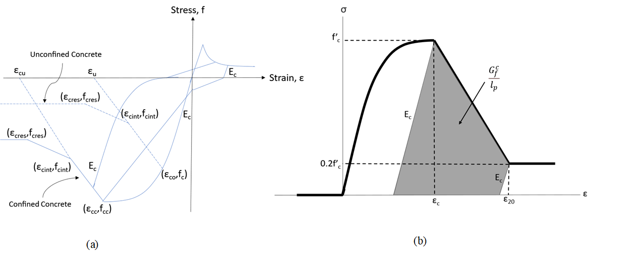
Figure 5 presents the uniaxial stress–strain response adopted for concrete. In this formulation, the parameter f\({}_{c}\) represents the peak compressive strength reached at a strain level of \(\varepsilon_0\), whereas \(\varepsilon_u\) corresponds to the ultimate strain capacity of unconfined concrete. The compressive strength of the concrete is used to calculate the model’s parameters. In this model, \(\varepsilon_0\) was taken to be 0.002. The ultimate strain \(\varepsilon_u\) of concrete is modified by accounting for mesh-size effects as described by Demirtas et al. [25]. To ensure computational stability, the tensile strain capacity of concrete was assigned a high value (e.g., 1.0), as shown in Figure 5, to prevent premature tensile failure.
The Reinforcing Steel material model in OpenSees is used, which is based on Chang and Mander [36] uniaxial steel model. The backbone curve shown in Figure 6 is the stress-strain behavior of the reinforcing bar. The average strain at the beginning of strain hardening \(\varepsilon\)\({}_{sh}\) is taken as 0.008 mm/mm, whereas the strain corresponding to ultimate strength \(\varepsilon\)\({}_{su}\) is set to 0.08 mm/mm.
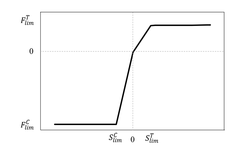
The reinforcing bar slip behavior was modeled using zero-length springs and the BarSlip uniaxial material model in OpenSees, as shown in Figure 7. \(S^C_{lim}\) and \(S^T_{lim}\)are the compression and tension slip limits, respectively. \(F^C_{lim}\) and \(F^T_{lim}\) represent the force limit in compression and tension, respectively. In OpenSees, the BarSlip material model, which is a uniaxial material model, is defined using the Pinching4 material model, considering the compressive strength of the concrete, the elasticity modulus, the yield, and the ultimate strength of the reinforcing steel, as well as the diameter and amount of reinforcing bars to compute the backbone curve.
In the numerical simulations, a lattice discretization with a grid spacing of 0.1 \(\mathrm{\times}\) 0.0875 m is adopted in OpenSees to represent the critical regions of the SP3 specimen. Experimental observations from the pseudo-dynamic tests indicated that damage was not limited to the beam–column joints but also developed at the column ends. Accordingly, the lattice mesh is extended along the columns over a finite length to adequately capture damage evolution within the plastic hinge zones. The configuration of the lattice model together with the nonlinear force-based beam–column elements is illustrated in Figure 8. Additional lumped masses are assigned at the beam ends to ensure accurate representation of inertia effects during the dynamic analyses.
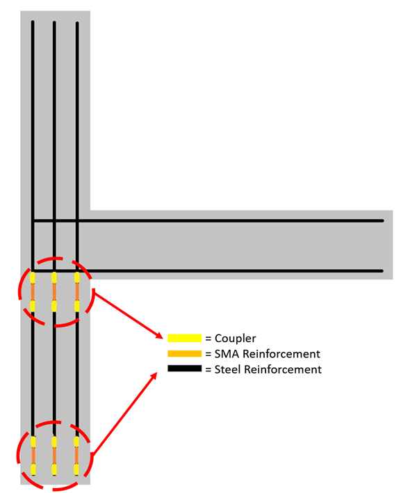
Various techniques, including near-surface mounted (NSM) reinforcement, embedded reinforcement in shotcrete layers, and externally anchored reinforcements, have been employed for retrofitting applications using SMA bars and plates (Figure 9). In this study, a retrofitting strategy similar to the NSM method is employed for the SP3 specimen.As illustrated in Figure 10, the steel reinforcement in the plastic hinge region at the column ends is replaced with Shape Memory Alloy (SMA) rebars. This replacement is not applied to the reinforcements in the BCJ, as seismic damage in this region primarily results from shear damage due to lack of transverse reinforcement in the joint panel. Furthermore, in existing three-dimensional building configurations, the presence of out-of-plane beams restricts the feasibility of replacing longitudinal bars within the BCJ panel. The connection between SMA and steel rebars in the plastic hinge region is assumed to be achieved through mechanical couplers, consistent with practical applications reported by Pareek et al. [37].
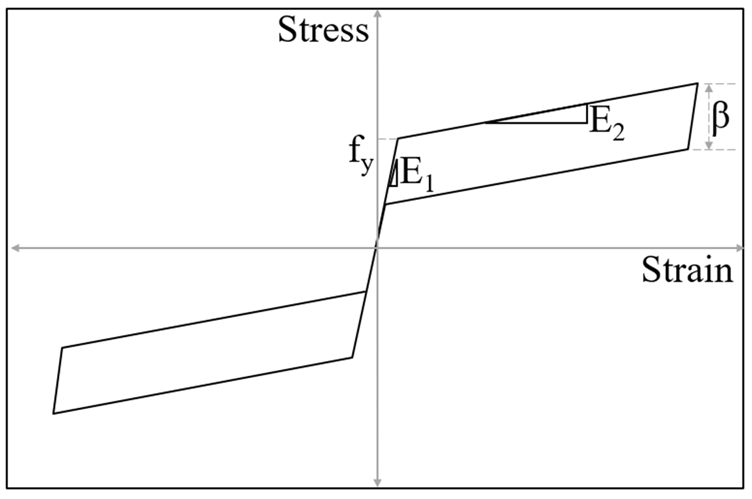
Two types of SMA materials, Cu-Al-Mn and Ni-Ti, are used as reinforcement materials in different cross-section configurations. In each configuration of the RC column section, the existing steel rebars were replaced with the selected SMA rebars in the plastic hinge region, as shown in Figure 10. The SelfCentering material model available in OpenSees was used as the material model for the SMA rebars (Figure 11). This model assumes a perfect re-centering capability of the SMA material. The SelfCentering model, although appropriate for numerical approximation, includes multiple simplifying assumptions. It idealizes SMA behavior as symmetrical in tension and compression, disregards thermal effects, and models stress-strain behavior with individually linear segments, ignoring cyclic degradation. Moreover, it assumes perfect re-centering without residual strain accumulation. Such assumptions may result in an overestimation of performance during extended or multi-directional cyclic loads. However, for comparative purposes among rebar layouts, the model offers consistent benchmarking. The numerical values for modelling parameters of Cu-Al-Mn and Ni-Ti materials shown in Figure 11 are provided in Table 3.
| Cu-Al-Mn [13] | Ni-Ti [39] | |
|---|---|---|
| E\({}_{1}\) (MPa) | 25000 | 64500 |
| E\({}_{2}\) (MPa) | 5 | 372 |
| f\({}_{y}\) (MPa) | 179.3 | 365 |
| Beta (%) | 10 | 59 |
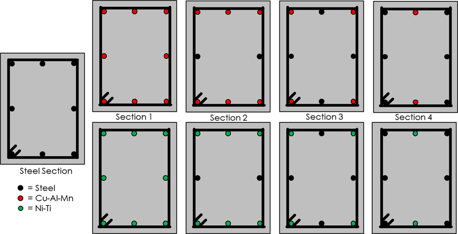
Despite the increasing application of SMA materials in retrofitting existing structures, the material cost of SMAs remains higher than that of conventional steel materials [38]. Thus, optimizing the amount of SMA material is essential to achieve a cost-effective retrofitting solution. Consequently, as shown in Figure 12, SMA materials are used in different configurations in the critical cross-sections of the first story columns only, which were exposed to severe flexural damage during the pseudo-dynamic testing (Figure 3a). In these cross-section configurations, both the amount of SMA bars and their location are varied. The general layout of the longitudinal rebars is kept the same for all configurations (Figure 12). Additionally, steel transverse reinforcement is employed with the same spacing and detailing in all RC sections.
The SP3 specimen, whose parameters are elaborated in Section 2, was subjected to the ground motion records applied during the pseudo-dynamic testing. The interstory drift ratio and the residual displacement demands are considered to be the critical measures of the seismic damage level of both structural and nonstructural components. Figure 13 shows the hysteretic behavior in terms of the first story shear force and interstory drift ratio for various column section configurations because the first story of the tested frame was where structural damage mostly occurred.
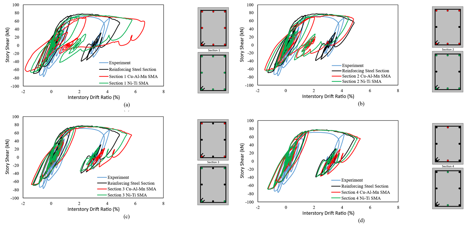
The reference section (i.e., fully reinforced by reinforcing steel) accurately estimated the peak story shear force and residual displacement obtained from the experimental results. The first-story shear force remains at similar levels in Section 3 and Section 4 configurations of Cu-Al-Mn and Ni-Ti SMAs. However, when SMA reinforcement was employed throughout Section 1, the peak interstory drift ratio was significantly higher than in the steel reinforced section. Nevertheless, peak interstory drift ratios are closer to the steel reinforced section in Sections 2 and 4. Furthermore, residual displacements in Sections 1 and 2 are well below those in the steel-reinforced section, while in Sections 3 and 4, it is seen that the residual displacements are close to or more than those in the steel-reinforced section. This indicates that the steel reinforcement rebars in Sections 3 and 4 dominates the structural response. The added SMA bars in these sections are not as effective as in the case of Sections 1 and 2 in terms of residual displacements.
The peak values of the drift ratio and the residual drift at the first story are calculated and compared for the investigated cross-section configurations against the experimental response. The configuration reinforced with Ni-Ti SMA bars demonstrated lower peak interstory drift ratios than its Cu-Al-Mn (Figure 14). This trend also holds for the residual drift ratio, except for Section 1. In Section 1, the peak drift ratio of the Ni-Ti SMA reinforced model is 5.5%, while the peak drift ratio of the Cu-Al-Mn SMA reinforced section is 7.5%. However, the residual drift ratio of Section 1 is at a similar level for the two SMA materials. Peak interstory drift ratio and residual drift ratio in Sections 3 and 4 are similar to the steel reinforced reference section. Peak drift ratio demands on Section 2, both Ni-Ti SMA reinforced and Cu-Al-Mn SMA reinforced sections, are determined to be the lowest values among the considered sections (4.5%-5.0%). In addition, the residual drift ratio in Section 2 is calculated as 1.5%, significantly less than the other sections except for Section 1. Comparing Sections 1 and 2 in terms of residual displacements, due to the insignificant difference, it can be inferred that there is no need to use SMA rebars for the entire longitudinal rebar configuration. An optimal SMA rebar layout needs to be sought to achieve the most favorable structural response in terms of both peak and residual displacements, while minimizing the amount of SMA material used.
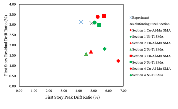
These results emphasize that a targeted partial replacement strategy, optimized for SMA placement, may yield better performance than full replacement. Residual drift reduction in Section 2 reaches up to 65% compared to the reference frame, while peak drifts are also improved relative to other configurations. It should be noted that while the optimized SMA layouts demonstrate significant reductions in residual interstory drifts, their effect on peak drift which governs structural damage is relatively limited in certain configurations. As such, the proposed retrofitting strategy is primarily beneficial for enhancing post-earthquake serviceability rather than preventing damage. In practice, SMA retrofitting may be more effective when integrated with global strengthening techniques to ensure both damage mitigation and re-centering capacity. This observation is consistent with previous findings, where SMA–ECC jacketing was shown to primarily improve re-centering ability rather than peak drift control [20], and SMA spirals or SMA–FRP composites effectively minimized residual deformations in RC structures [21].
SMAs are increasingly used in retrofitting of sub-standard reinforced concrete buildings, due to their inherent superelastic behavior, allowing them to return to their original shape after load removal. However, given the relatively high cost of SMAs, it is essential to optimize their use by applying them in quantities that yield the most effective structural performance. In this study, Ni-Ti and Cu-Al-Mn SMA rebars are employed in different layout configurations within the plastic hinge region of the first story columns of a 3-story, 3-span RC frame with non-seismic detailing and substandard structural configuration. The response of the experimentally tested RC frame was reproduced in the OpenSees platform using the lattice modeling technique. In this technique, concrete and reinforcement elements in the critical position of the RC frame are modeled as truss elements by using their own material properties. The created models underwent nonlinear time history analysis under the successive ground motion records used during the pseudo-dynamic testing. The peak drift ratio and residual drift ratio of the first story were examined for each developed numerical model that investigates optimal configuration of SMA bars when enhancing the seismic performance.
The following findings are drawn from the analysis results of the investigated frame having variable cross-section configuration formed by SMA rebars.
For the same section configuration with different SMA rebars, sections with Cu-Al-Mn rebars caused a higher peak drift ratio than the Ni-Ti section (e.g., 7.5% vs. 5.5% in Section 1). This difference may be attributed to the lower yield strength and post-yield behavior of the employed Cu-Al-Mn compared to Ni-Ti, leading to increased displacement demands in sections with Cu-Al-Mn rebars, thereby potentially dissipating more seismic energy.
Except for Section 1, which has the same rebar material for all longitudinal bars, sections with Cu-Al-Mn rebar have resulted in less residual displacements compared to the sections with Ni-Ti rebar. However, the difference in the residual displacements for two different SMA materials is not as distinct as in the case of peak displacements.
The smallest residual displacement demands (as low as 1.5%) are achieved with Sections 1 and 2. There is no need to use SMA material for all longitudinal bars in the critical cross-section. Therefore, an optimum SMA rebar layout needs to be sought to achieve the most favorable structural response as a form of peak and residual displacements, along with minimizing the amount of SMA material used.
The presence of steel longitudinal rebars at the top and bottom bar layer dominates the response of the cross-section. SMA rebars are not effective in Sections 3 and 4, which resulted in similar residual displacements with the original steel rebar layout. To achieve the desired level of seismic response, the effectiveness of the cross-section needs to be investigated for a cost-effective retrofit solution when the SMA materials are used as longitudinal reinforcing bars.
The present study assumes an idealized shape memory alloy behavior by employing the Self-Centering material model, which ignores cyclic degradation, asymmetric response, and temperature dependency. These simplifications must be taken into account before generalizing the findings. The retrofitting approach was exclusively implemented on the first-story columns. No strengthening was executed in the BCJ zones, which are also critical under seismic loads. The numerical analysis was confined to 2D planar response, excluding out-of-plane or torsional effects. No cost-performance analysis or economic optimization was specifically conducted.
Yunus Demirtaş: Writing – original draft, Validation, Methodology, Formal analysis, Data curation, Conceptualization. Özgür Avşar: Writing – review & editing, Methodology, Conceptualization, Supervision.
Some or all data, models, or codes that support the findings of this study are available from the corresponding author upon reasonable request.
The authors declare that they have no known competing financial interests or personal relationships that could have appeared to influence the work reported in this study.