

In recent years, researchers in earthquake engineering have developed hybrid passive dampers as a two-phase protection system for buildings and structures. These protection systems improve the seismic resilience of structures by dissipating energy efficiently by activating one mechanism at low to medium levels and another mechanism at higher levels. Lee, Kang & Kim [1] combined a slit damper and a friction damper for seismic protection. The friction damper operated under low peak ground acceleration (PGA), while both the friction and slit dampers functioned together under high PGA conditions.
A five storey steel building was modelled in Perform -3D Software. The hybrid damper demonstrated the ability to dissipate 57 % to 70 % of hysteretic energy across varying peak ground acceleration levels. Lee, Kang & Kim [1] recommended the use of a slit damper combined with a rotational friction damper as a hybrid system for steel structures. The assembly comprised a steel slit plate secured with high-strength bolts and nuts, along with a friction pad. Experimental findings revealed that the hybrid damper outperformed individual dampers by 50%. An eight-story RC building was modelled in SAP2000 and retrofitted with the hybrid damper, where numerical analysis indicated a 50% reduction in roof displacement. Yan et al. [2] manufactured a device that integrated lead extrusion damper and friction damper. The hybrid damper exhibited a hysteretic load of approximately 60 kN and a displacement of 30 mm.
Chukka & Krishnamurthy [3] proposed retrofitting an eight-story RC building using a hybrid damper consisting of an XADAS and a friction damper. Experimental results showed that the XADAS damper force 60 kN at a displacement of 10 mm, while the friction damper force 50 kN at the same displacement. The hybrid configuration achieved a combined resistance of 100 kN at 10 mm displacement. Numerical results revealed that the hybrid device provided superior seismic performance, achieving reductions of 66.6% in the average maximum drift ratio, 68% in top displacement, and 56% in base shear, thereby outperforming both XADAS and the friction damper. Avestaeifar & Khezrzadeh [4] combined variable steel strips with friction damper. The proposed hybrid device achieved a maximum energy dissipation of 350 kJ. Li, wang & Cao [5] proposed recentring hybrid damper by integrating fluid viscous damper and friction spring damper.
The experimental results showed that the recentring hybrid damper could take maximum load of 50 kN with 15 mm displacement. In order to enhance the seismic behaviour of medium rise steel building, Golmoghany & Zahrai [6] proposed a device with vertical shear panel damper and friction damper. The hysteresis curves displayed a stable performance with increase in ductility ratio by 87 % and reduction in drift ratio and peak displacement by 17 %. Zhang et al. [7] developed a hybrid damper with X type slotted damper and friction plates in series. The hysteresis curve showed the maximum load of 40 kN with 25 mm displacement. Lu et al. [8] suggested a hybrid damper by joining strip damper with friction damper. The brass plate was used as inner plate for friction damper and a sliding slot was provided. The hysteresis curve showed a force around 100 kN with 40 mm displacement. This hybrid damper was adopted for steel buildings. Ke et al. [9] devolved a hybrid damper with tapered strip damper and variable friction damper. The hysteresis curve showed around 180 kN force with 20 mm displacement, and it was recommended for industrial structures. A thorough literature review on hybrid dampers reveals that only a few types of passive dampers have been combined and designed specifically for steel structures, with limited research conducted on their application in concrete structures [10]. Recently, Arvind, Santhi & Malathi [11] fabricated a new hybrid damper device by combining comb teeth damper (CTD) and friction damper (FD) specifically tailored for use in RC structures under Indian conditions. The dimensions of the comb teeth damper (CTD) were determined through a parametric study by varying the number of teeth (4 nos and 5 nos) and thickness of the plate (5 mm, 10 mm, 15 mm, 20 mm, 25 mm and 30 mm). The results indicated that a configuration with 5 CTD with 15 mm thickness provided the better performance [12].

The dampers CTD, FD and CTFD were fabricated with the dimensions as given in Figure 1 and tested under monotonic lateral loading using A-type self-restraining 3D loading frame. A 50-ton capacity load cell was attached to an actuator, which was used to apply loads to the damper specimens. The resulting displacements were measured using an LVDT with a 200 mm displacement capacity. The experimental setup for monotonic lateral load and the salient results of all the dampers is shown in Figure 2 and Table 1, respectively. In the hybrid damper, the CTD yielded first and carried the load; once it reached its limit, the load was transferred to the FD. From that point, both devices shared the increasing load until they eventually failed. From the results it was observed that CTFD has higher lateral load capacity, ductility ratio and energy dissipation capacity than CTD and FD, thereby showing higher performance.

| Type of damper | Yield load (kN) | Ultimate load (kN) | Ductility ratio | Energy dissipation (J) |
| CTD | 40 | 108 | 4.4 | 4800 |
| FD | 45 | 125 | 3.12 | 6800 |
| CTFD | 70 | 210 | 5.8 | 8500 |
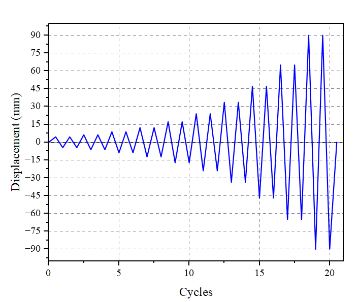
In this study, the comb teeth damper (CTD), Friction damper (FD) and Hybrid damper (CTFD) were modelled in ABAQUS software to study their behaviour under cyclic loading. The material used for analysis was mild steel E250A. The stress-strain curve obtained from the tensile test was the input for material property. All the damper models utilized C3D8R elements. The loading protocol was followed from FEMA 461 as shown in Figure 3. The bottom portion was fixed and the upper portion of the damper was subjected to the cyclic loading. Figures 4 to 6 show the FE model, loading conditions of CTD and the stress contour of CTD, respectively.

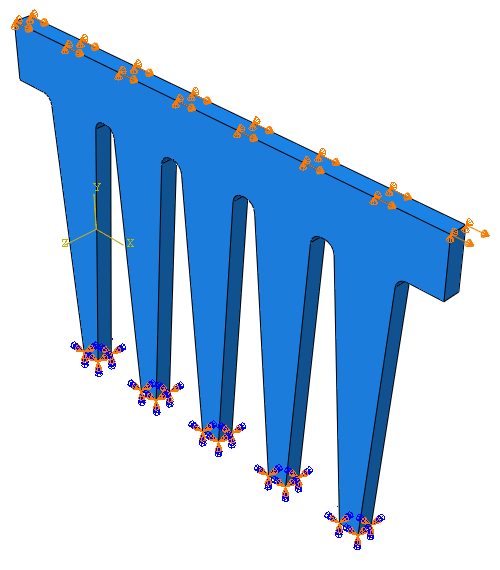

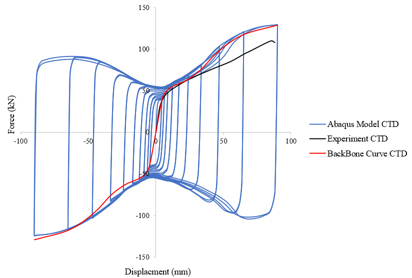
The hexagonal mesh of 10 mm was evenly generated in all the dampers. There was no lapping or uneven mesh division or mesh error was found. Figure 7 shows the comparison curve of numerical model, experiment CTD and backbone curve of CTD. The numerical model’s yield load of 50 kN and 5 mm displacement align with the yield of experimental results, and the backbone curve was derived from the numerical model.
Similarly, the friction damper utilized the same material, loading protocol, and mesh size of 10 mm as those used for the CTD. Figure 8 shows the support conditions of friction damper. In the experiment, the corner of the friction damper (FD) was bent, and a similar bending and deflection were observed in the numerical analysis as shown in Figure 9. Figure 10 shows the comparison results of numerical model, experiment and backbone curve of FD. The FD has stable hysteresis curve. The numerical model showed a yield load of 45 kN and a displacement of 13 mm, which was closely matched with the experimental findings. The backbone curve was developed based on the numerical model. The ultimate load for the friction damper (FD) in the numerical analysis was 120 kN at 90 mm displacement, whereas the experimental results showed an ultimate load of 86 kN at 125 mm displacement.


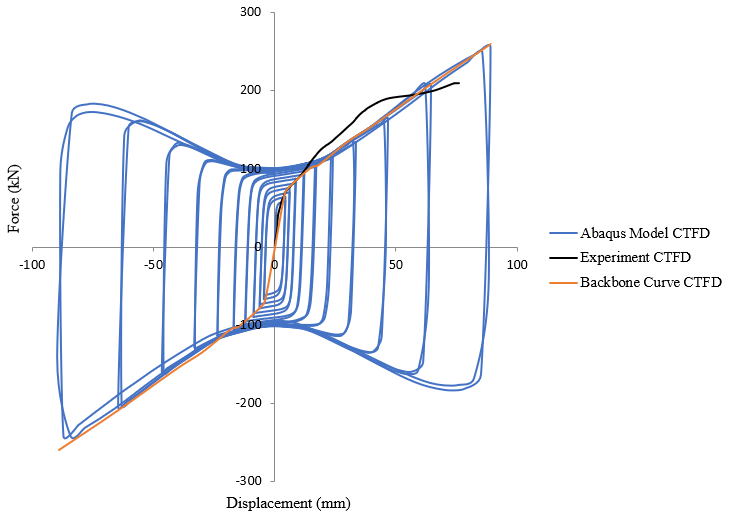
The hybrid damper (CTFD) was also modelled using C3D8R element. Likewise, the hybrid damper utilized the same material, loading protocol, and mesh size of 10mm as those used for the CTD, FD. The hybrid damper with mesh and loading direction is shown in Figure 11. The stress contour of hybrid damper is shown in Figure 12. Figure 13 shows the comparison curve of numerical model, experiment CTFD and backbone curve of CTFD.


The numerical model showed a yield load of 75 kN and a displacement of 5 mm, which closely matched with the yield load and displacement of experimental findings. The ultimate load for the hybrid damper (CTFD) in the numerical analysis was 250 kN at 90 mm displacement, whereas the experimental lateral load results showed an ultimate load of 210 kN at 76 mm displacement.
The energy dissipation by the hybrid damper was 75 % and 25 % more than that of CTD and FD, respectively. The numerical model’s yield load and displacement was closely attained with the experimental results.
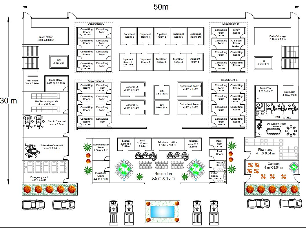
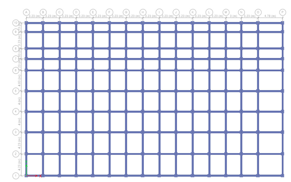
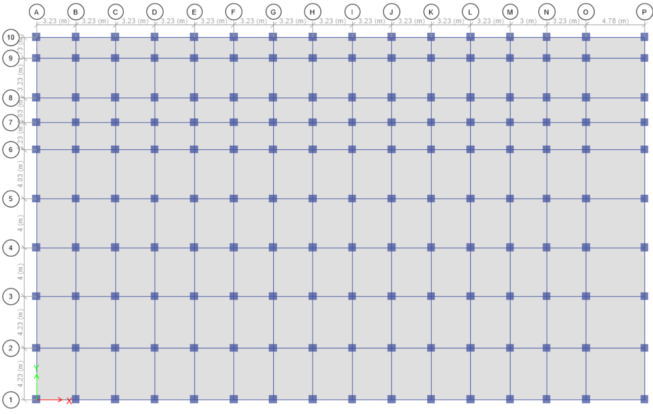
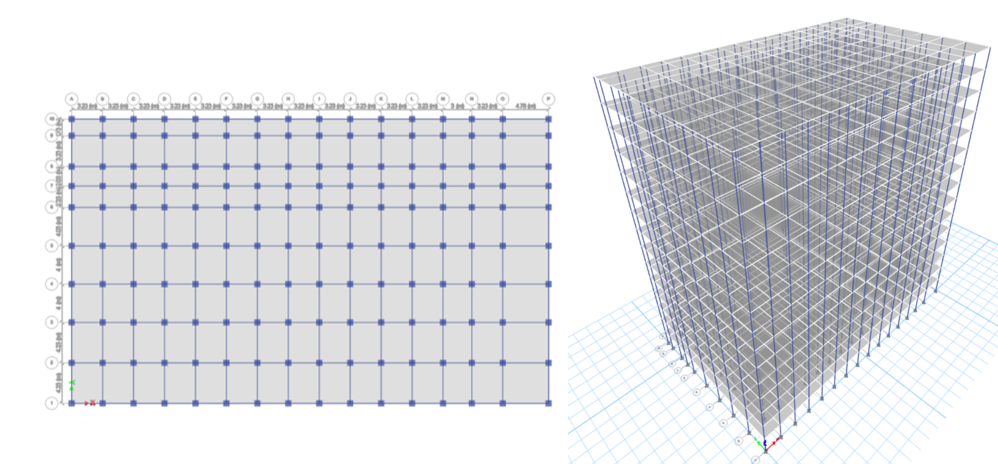
Hospitals are essential facilities in a society, serving dual roles during disasters: they provide immediate medical care and can serve as emergency shelters [13, 14, 15, 16]. The structural integrity of hospital buildings is paramount, as they need to withstand seismic events and continue functioning to save lives during disaster response [17, 18, 19, 20, 21, 22]. Figure 14 shows the architectural plan of the hospital building under study. The column layout of the hospital building is shown in Figure 15. The floor height of the building was considered as 3.5 m. The overall height of the building was 52.50 m, and the plan area was 50 m x 30 m. The hospital building was designed by considering the maximum possible functionalities as per the standard of IS 12433 part 1, hospital with teaching facility given in IS 10905 part 2 & 3: 1984 falls in category E with 750 bedded, NBC 2016 and TNCDBR 2019. Figures 16 and 17 show the plan and elevation view of hospital building modelled in ETABS without damper.
The dimensions of the structural members and loads are common on all floors as given in Table 1. As per the code of Indian standard IS 1893:2016, the importance factor for critical and lifeline structures is 1.5. The response reduction factor was taken as 5 and seismic Zone V was considered. The soil type considered was medium. The end length offset was given as 1 and diaphragm was also provided. Fe 415 grade steel was used for both main reinforcement and secondary reinforcement. For dynamic analysis, the Multilinear Plastic Link (MLP) element offers a sophisticated method for simulating damper behavior across different degrees of freedom. The MLP element demonstrates a distinctive force-displacement relationship characterized by an initial elastic phase that transitions to a perfectly plastic state upon reaching the yield force [3, 12, 23, 24, <a href="#25"25]. The dampers CTD, FD and CTFD were modelled as non-linear link element, MLP. Based on the experimental curve from Figure 2, the input for MLP was given for each damper.
| Grade of concrete | M 25 |
|---|---|
| Poisson’s ratio | 0.2 |
| Beam size | 300 mm x 400 mm |
| Column size | 650 mm x 650 mm |
| Slab thickness | 150 mm |
| Angle section | 50 mm x 50 mm x 6 mm |
| Live load on floors | 3 kN/m\(^{2}\) |
| Live load on terrace | 1.5 kN/m\(^{2}\) |
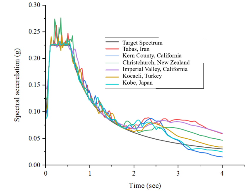
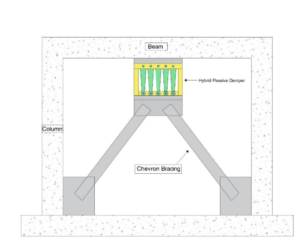
Non-linear dynamic analysis was done by using the scaled ground motion data (Figure 18) to assess the seismic performance of dampers placed in the hospital building. In real-life implementation, generally a chevron bracing is used to place the damper in the building frame as shown in Figure 19. The strategic placement of dampers is critical in improving a building’s seismic performance, specifically in reducing top displacement, inter storey drift and maximizing energy dissipation [26, 27, 28].
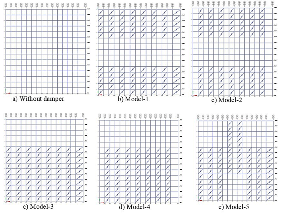
In this study, five different positions and locations of dampers were considered along the building height with CTD, FD and hybrid CTFD to determine the seismic performance of the hospital building. The different positions of dampers are shown in Figure 20. Based on the literature, five different damper positions were chosen to evaluate their effectiveness in terms of energy dissipation, inter-storey drift, and top displacement. In Model 1 and 2, the focus was on reducing base shear and top displacement, with odd and even placements adopted for uniform distribution. In model 3 and 4 was aimed to reduce interstorey drift and balanced distribution of damper across the frame. In model 5 , focus was on reducing interstorey drift and top displacement as damper were damper in middle and upper storey [29 30, 31, 32, 33] .
The dampers were placed in alternate bays and the number of dampers was fixed, only the position of dampers was changed as described in Table 3.
This section thoroughly examines the seismic performance of G + 14 storey RC hospital building with and without dampers in terms of top displacement, inter storey drift and energy dissipation. The hospital building was subjected to nonlinear dynamic analysis with six different PGA ranging from 0.035 g to 0.68 g and the results are as follows.
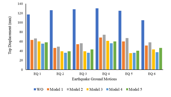
The seismic performance of the building without damper (WO) was taken for comparing the seismic responses of the building with dampers. The top displacement values for the building without damper were found to be 117 mm,126 mm,128 mm,130 mm,125 mm and 105 mm for the six different ground motions. When comparing the response of the building with CTD, it was observed from Figure 21 that the reduction was 15 %, 13 %, 15 %, 16 % ,21 % for model 1 to model 5, respectively. The friction damper reduced 15 %, 17 %, 19 %, 20 % and 23 % from model 1 to model 5, respectively. It was found that the building with friction damper reduced the top displacement (Figure 22) in the range of 18 to 23 % for different PGAs.

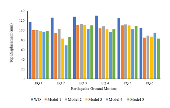
The hybrid CTFD models showed better performance in terms of top displacement under low to high PGAs when compared to building without the damper. The top displacement for CTFD is shown in Figure 23. It was observed that the reduction was significant and found in the range of 60 to 70 %, showing the effectiveness of the hybrid CTFD. Model 4 and Model 5 was consistent in reduction of top displacement in all dampers.
The inter- storey drift ratio was restricted to 0.002 for the safety of the hospital building. The inter-storey drift for WO model under earthquakes considered was beyond the specified drift. The inter-storey drift of the comb teeth damper was within the limit for three ground motions, say, EQ1, EQ2 and EQ 3 as shown in Figure 24. The inter-storey drift ratio for FD and CTFD is shown in Figure 25 and Figure 26, respectively. The building with FD showed good performance in terms of inter- storey drift for EQ 2 and EQ 6 in all models except Model 2. The Model 5 showed better performance among the models considered.
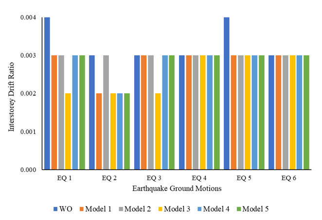
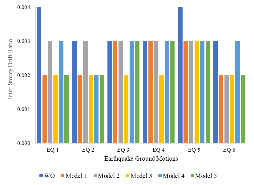
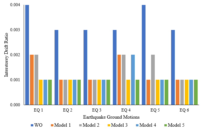
The inter-storey drift of the building with hybrid CTFD, the model 1 to model 5 was within the limit. The model 3 and 5 were consistent in performance. The model 4 was better compared to model 1 and model 2 by five earthquake ground motions within the limits. The Model 5 performed better than other models and showed inter- storey drift was within the limit under all earthquakes.
During an earthquake, elastic strain energy is released. The building absorbs this energy, leading to structural damage and potential collapse. In contrast, a damper absorbs the seismic energy and dissipates it, reducing the structural damage to the building. Eq. (1) shows the various components of the energy dissipated.
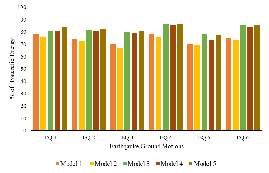
\[\label{eq1} E_{I}= E_{k}+E_{P}+E_{D}+E_{H}, \tag{1}\] E\({}_{I}\) is input seismic energy, E\({}_{k}\) is referred as kinetic energy, E\({}_{P}\) is potential energy, E\({}_{D}\) is global damping energy and E\({}_{H}\) is hysteresis energy. The ratio of hysteretic energy to input seismic energy is the amount of seismic energy dissipated by the device in percentage. Figure 27 shows the energy dissipation of CTD.
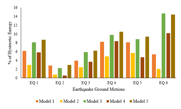
The WO model has no hysteresis energy, and all input seismic energy was transferred to the structural members causing excessive deflections and deformations. The comb teeth damper dissipated seismic energy with maximum of 15 %. The Model 2 performed very poor when compared to other models. The Model 5 was consistent in all earthquake ground motions. The overall seismic energy dissipated was around 15 %, the rest of energy 85 % is dissipated by the structural members. The Model 5 was the best model for the building with comb teeth damper. Figure 28 shows the energy dissipation of FD. The friction damper overall dissipated around 28 % for model 3 and 5. The Model 2 performs very poor compared to other models. The model 1and 4 had shown average performance. Figure 29 shows the energy dissipation of CTFD. The hybrid CTFD showed around 74 %, 72 %, 82 %, 81 % and 83 % energy dissipation for models1, 2, 3, 4 and 5, respectively.


A comprehensive series of 96 nonlinear dynamic analyses was performed to investigate the crucial relationship between damper placement and the seismic performance in the hospital building. The earthquake ground motion data were classified as 3 categories, namely, low PGA, low to medium PGA, and low to high PGA. The low PGA consisted of EQ 1 and EQ 2, the low to medium PGA contains EQ 1, EQ 2, EQ 3 and EQ 4 and, low to high PGA has EQ 1, EQ 2, EQ 3, EQ 4, EQ 5 and EQ 6. The determining parameters were top displacement, inter-storey drift and seismic energy dissipated.
The Model 5 of CTFD performed better than all other models in terms of inter- storey drift, top displacement and energy dissipation under all PGAs.
This study introduced and validated a novel Comb Teeth–Friction Damper (CTFD), a hybrid passive energy dissipation device specifically designed for reinforced concrete (RC) structures. The damper’s numerical model closely reproduced the experimentally obtained yield load and displacement, confirming the accuracy and reliability of the proposed analytical framework. The CTFD demonstrated excellent energy dissipation capacity, approximately 75% and 25% higher than that of the Comb Teeth Damper (CTD) and Friction Damper (FD), respectively.
A series of nonlinear time history analyses were conducted to evaluate the seismic performance of a hospital building equipped with CTD, FD, and CTFD systems across five different damper placement configurations and multiple levels of peak ground acceleration (PGA). Among these, the Model 5 configuration, with dampers distributed in the middle and upper storeys, provided the most favorable results. The hybrid system achieved nearly 80% total energy dissipation, maintained inter-storey drift ratios within 0.002, and reduced top displacement by about 60% compared to the uncontrolled frame. These findings confirm that the proposed hybrid damper and its optimal placement strategy can substantially enhance the seismic resilience of critical facilities.
The key novel contributions of this work include:
1. The development, fabrication, and multi-stage validation of a new hybrid passive damper (CTFD) for RC structures.
2. A comprehensive comparative analysis demonstrating the synergistic performance of the hybrid system relative to its constituent damper types.
3. The introduction of a rational damper placement strategy that provides practical guidance for improving the seismic performance of essential buildings such as hospitals.
Despite its promising results, the study has certain limitations. The damper placement strategies were evaluated through comparative analysis rather than formal optimization; the system-level seismic assessment was purely numerical and awaits large-scale experimental verification; and the analytical model did not account for potential effects such as soil–structure interaction or three-dimensional torsional responses.
Future work will address these aspects by:
1. Applying optimization algorithms (e.g., genetic algorithms) to determine the optimal sizing and distribution of CTFDs.
2. Conducting shake table tests on multi-storey RC specimens equipped with the CTFD in the Model 5 configuration.
3. Performing a life-cycle cost–benefit analysis to benchmark the CTFD system against other seismic retrofitting and damping technologies.
Overall, the research demonstrates that the CTFD system, when strategically positioned, offers a robust, efficient, and practical solution for enhancing the seismic performance and resilience of critical infrastructure across a wide range of seismic intensities.