

Shake tables are essential tools in earthquake engineering laboratories, providing a means to experimentally analyze the dynamic response of structural systems under simulated seismic events. These platforms are designed to replicate ground motion by applying controlled single or multiple degrees of freedom displacement histories to a moving plate that excites the test specimen [1]. Well-equipped research facilities around the world employ large-scale shake tables to conduct advanced testing on full-scale structures and seismic protection devices, often in combination with soil simulators that replicate subsurface deformation during earthquakes [2].
Shake table testing serves a wide range of purposes, including evaluating the seismic resistance of structural models, determining dynamic properties such as natural frequencies and damping ratios, examining soil-structure interaction effects, and validating the performance of new seismic isolators and energy dissipation devices. These systems also play a valuable role in education, helping students understand the fundamentals of earthquake-resistant design and the behavior of isolation systems [3].
Commercially available desktop shake tables typically focus on achieving high accelerations with minimal vertical load capacity, making them suitable for lightweight models and basic demonstrations. In contrast, a laboratory-scale shake table recently developed at the University of Salerno was designed to meet different objectives. This custom-built setup enables the testing of medium-scale seismic isolators and structural components by supporting large lateral displacements, substantial vertical loads, and high horizontal velocities. A key application is the experimental characterization of bioinspired sliding-stretching isolators (SSIs), which incorporate a deformable unit cell and combine sliding and stretching mechanisms to dissipate seismic energy. Drawing inspiration from biological systems–where resonance is tuned for efficient motion–these devices aim to avoid resonance with seismic frequencies by adjusting their nonlinear stiffness through elastic elements [4]. The design emphasizes sustainability, allowing the components to be fabricated using 3D printing and eco-friendly or recycled materials.
This paper presents the design methodology, assembly process, and performance characteristics of the custom shake table system developed for seismic isolator testing. Unlike conventional educational setups, this table is capable of imposing complex displacement histories under significant loads, enabling the evaluation of isolators used to protect sensitive equipment, artworks, or critical infrastructure components.
The structure of the paper is as follows. Section 2 details the shake table’s design and assembly. Section 3 introduces a finite element model used to simulate performance under demanding conditions. Section 4 presents experimental validation results, including a test on a prototype SSI. Section 5 concludes with key findings and future research directions.
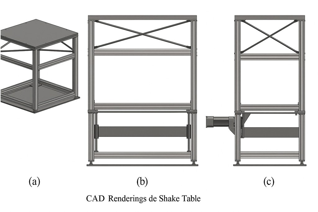
The custom-built shake table was designed with the primary objective of replicating realistic seismic loading conditions for small to medium-scale seismic isolator prototypes. To do so, the system must deliver accurate and repeatable horizontal motions, while simultaneously applying vertical loads that mimic the weight of superstructures. Unlike commercially available educational shake tables–which often prioritize high acceleration over displacement and vertical force–this setup emphasizes displacement capacity, load-carrying ability, and flexibility in motion profiles [5, 6].
To meet these objectives, several target performance criteria were defined, summarized in Table 1. These parameters guided the structural, mechanical, and electromechanical design of the system, ensuring its ability to test isolators intended for critical applications such as heritage preservation, medical equipment stability, and high-value contents.
| Parameter | Value |
|---|---|
| Weight | 2.94 kN |
| Dimensions (L × W × H) | 2570 × 1200 × 1000 mm |
| Base/Top Plate Dimensions | 700 × 700 mm |
| Vertical Distance (Base–Top) | 20–550 mm |
| Max Horizontal Force | 3 kN |
| Max Vertical Load | 30 kN |
| Max Displacement | ±200 mm |
| Max Frequency | 20 Hz |
| Max Velocity | 1 m/s |
| Max Acceleration | 3 m/s2 |
| External Beam Dimensions | 1800 × 900 mm |
| Central Beam Dimensions | 900 × 900 mm |
| Guideway Length | 1200 mm |
Smooth and precise horizontal motion is essential for accurately simulating earthquake displacement patterns. The shake table employs HIWIN-HG series linear guideways beneath the base plate to ensure low-friction, high-stiffness motion. These guideways are designed to sustain high dynamic and static loads while maintaining tight tolerances [8].
Each side of the moving base plate is supported by three SETEC HGW 25HC recirculating ball bearings, securely fixed with four M8 bolts per bearing. These bearings have a load capacity of up to 32.75 kN, which significantly exceeds the total dynamic load generated during operation, ensuring longevity and mechanical safety.
Vertical motion is enabled through Bosch Rexroth steel guide rods with a 25 mm diameter. These rods are mounted on the four corners of the setup and are equipped with Rexroth eLINE R1029 tandem linear bearings, allowing the top plate to move vertically while withstanding any horizontal forces transferred from the shaking base.
Horizontal motion is driven by a SETEC Isomove-E actuator (model IE 63), chosen for its ability to generate a wide range of displacement waveforms–sinusoidal, triangular, and rectangular–up to a maximum speed of 1 m/s and acceleration of 3 m/s2. These characteristics make it suitable for replicating both low-frequency tectonic movements and more intense pulse-type inputs [9].
| Symbol | Description | Value |
|---|---|---|
| P | Screw lead | 20 mm |
| Fe | Max dynamic load | 7500 N |
| Vout_max | Max output speed | 1000 mm/s |
| Cin_max | Max input RPM | 3000 rpm |
| Nin_max | Max input RPM | 3000 rpm |
| Smax | Stroke | 800 mm |
| amax | Max acceleration | 3 m/s2 |
| Parameter | Value |
|---|---|
| Max Load | 25 kN |
| Screw Diameter | 30 mm |
| Screw Lead | 6 mm |
| Nominal Ratio | 5:10 |
| Real Ratio | 5:10.33 |
| Motor Model | BMH1002P07F2A |
| Protection Rating | IP54 |
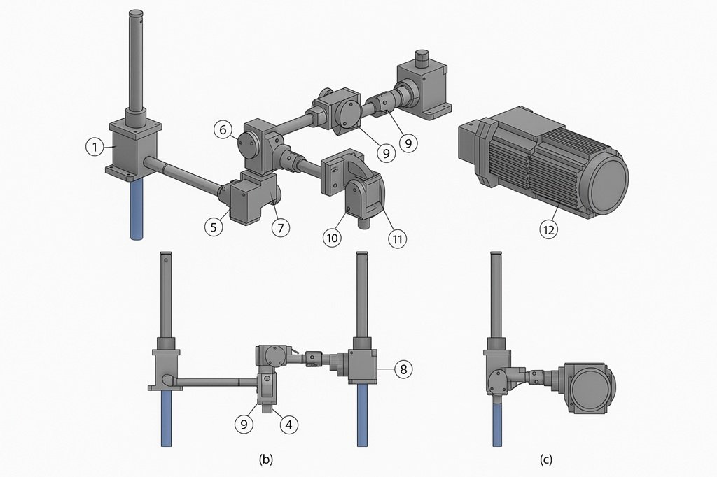
Vertical motion is achieved using four SETEC SEL 25 screw jack actuators, which apply a synchronized compressive load via a common transmission system. This system includes angular gearboxes and linkages that distribute the motion evenly across all four actuators. The entire vertical subsystem is driven by a Schneider Electric brushless motor (BMH1002P17F2A), offering high positioning accuracy and reliability during operation.
The electromechanical system is driven and regulated using Schneider Electric Lexium 32 servo drives, each tailored to its respective axis. The LXM32S 72A RMS model controls horizontal displacement, while the LXM32S 18A RMS model governs the vertical actuators. These drives interface with a Modicon TM262M15MESS8 motion controller, enabling real-time synchronization of movements with high responsiveness [10].
| Specification | Horizontal Motion | Vertical Motion |
|---|---|---|
| Model | LXM32S 72A RMS | LXM32S 18A RMS |
| Dimensions (W×H×D) | 108×270×237 mm | 68×270×237 mm |
| Voltage | 380–480 V | 380–480 V |
| Frequency | 50–60 Hz | 50–60 Hz |
| Nominal Power | 7 kW | 1.8 kW |
| Peak Output Current | 72 A (5 s) | 18 A (5 s) |
The system is programmed and tuned using EcoStruxure Machine Expert (SoMachine) software, where position, speed, and acceleration curves are defined and adjusted. Safety margins, soft limits, and emergency protocols are embedded within the control logic to ensure operational reliability.
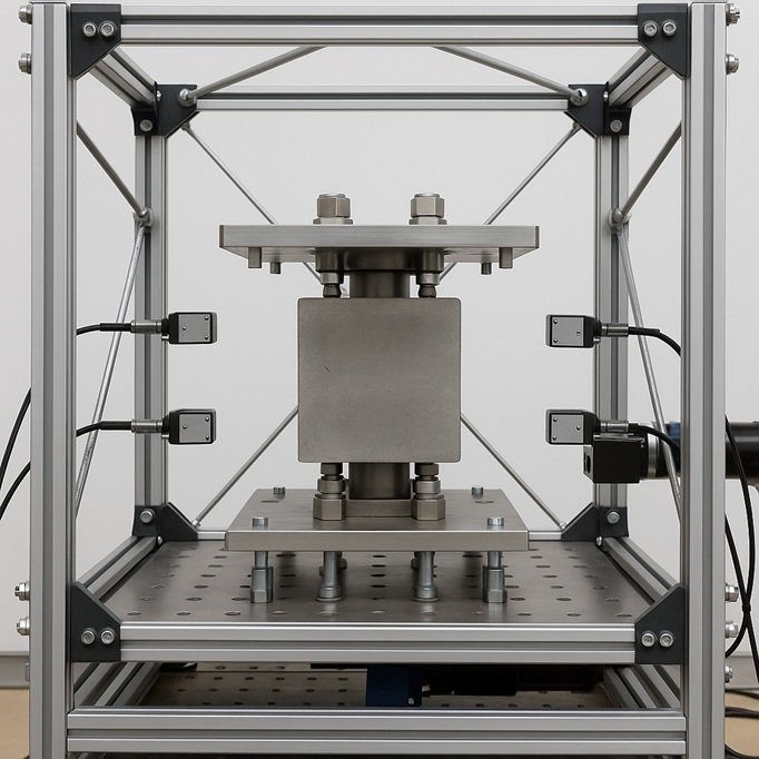
The fully assembled shake table is shown in Figure 3. It illustrates the integration of structural, mechanical, and control components into a compact and robust platform. The setup is grounded securely with anchor bolts, ensuring stability during dynamic tests. Wiring channels and sensor mounts are included for future automation and data acquisition system upgrades [11].

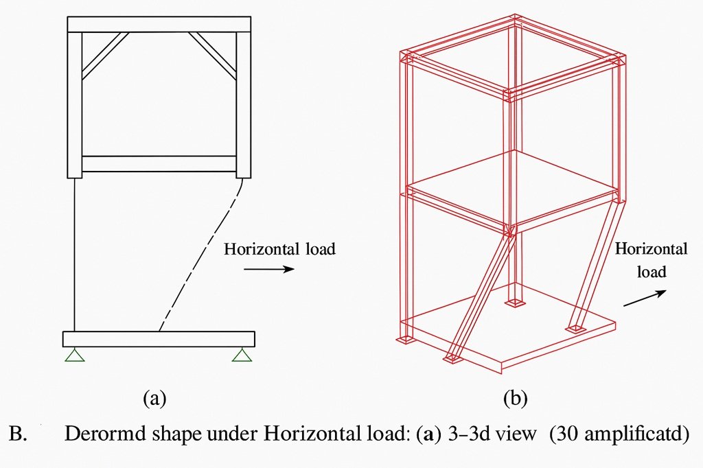
A comprehensive finite element modeling (FEM) approach was employed to validate the mechanical performance of the custom-built shake table under the most critical operational scenarios [12]. This analysis aimed to ensure that all structural components remain within elastic limits when subjected to maximum vertical and horizontal forces, and to evaluate the stiffness, deflection behavior, and stress distribution throughout the setup. The simulation was performed using SAP2000 (Computers and Structures, Inc.), a widely used software in structural engineering applications [13].
The finite element model accurately replicates the geometry of the constructed shake table, including all primary load-bearing components, actuator connection points, and boundary conditions. The model comprises 63 frame elements (beams, rods, and stiffeners) and 140 shell elements, used to simulate the top and base plates with high fidelity [14].
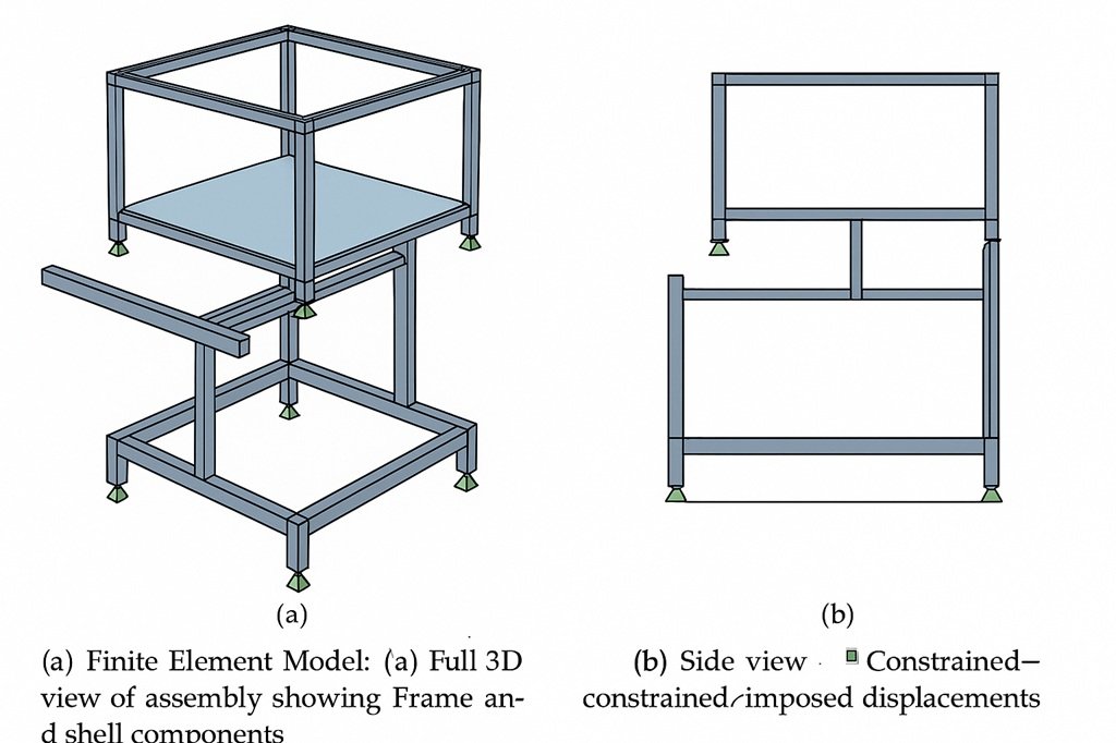
Two critical load cases were simulated:
The structure was discretized using linear beam elements for rods, stiffeners, and tie rods, and four-noded shell elements for plate surfaces. All elements were assigned cross-sections and thicknesses according to manufacturing specifications and CAD drawings.
| Component | Cross-Section | Element Type | Dimensions | Material |
|---|---|---|---|---|
| Tie-rods (cables) | Circular rod | Frame | Ø8 mm | A235 steel |
| Vertical guideways | Circular bar | Frame | Ø25 mm | Cf53 steel |
| Top plate | Solid plate | Shell | 20 mm thick | A235 steel |
| Base plate | Solid plate | Shell | 20 mm thick | Al 6082-T6 |
| Upper frame | L-profile | Frame | 60 × 6 mm | A235 steel |
| Stiffeners | Rectangular | Frame | 100 × 10 mm | A235 steel |
| Perimeter ribs | Rectangular | Frame | 100 × 10 mm | A235 steel |
| Material | Young’s Modulus (MPa) | Yield Strength (MPa) | Ultimate Strength (MPa) |
|---|---|---|---|
| A235 steel | 210,000 | 235 | 360 |
| Cf53 steel | 210,000 | 340 | 610 |
| Al 6082-T6 | 69,000 | 260 | 310 |
Stress analysis verified whether any structural elements exceeded their elastic limits. All components remained within the elastic range, with safety margins below yield stress values.
| Component | Max Stress (MPa) |
|---|---|
| Cables (tie-rods) | 107.69 |
| Vertical guideways | 201.11 |
| Top frame – X axis | 9.71 |
| Top frame – Y axis | 27.77 |
| Top plate stiffeners | 114.46 |
| Plate border ribs – X axis | 35.71 |
| Plate border ribs – Y axis | 25.00 |
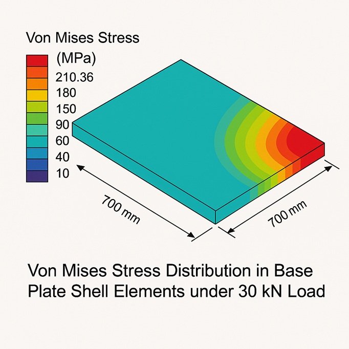
Deflection analysis was conducted under combined loading. The base plate exhibited a maximum vertical deflection of 2.89 mm. Under horizontal loading, lateral displacements were 2.58 mm (top plate) and 2.26 mm (top frame), all within acceptable limits.
To further improve stiffness and reduce bending during concentrated loading, intermediate load-spreading plates or pads are recommended.
The finite element simulations confirm that the shake table:
These results validate the structural design decisions and confirm the shake table’s readiness for experimental seismic testing under realistic loading conditions.
To verify the operational performance and mechanical integrity of the developed shake table, a series of experimental validation tests were conducted [15]. These tests were designed to assess the system’s ability to apply target vertical and horizontal forces, replicate prescribed displacement histories, and evaluate its performance under cyclic loading. The test campaign included both component-level validation and functional evaluation through the characterization of a sliding-stretching isolator (SSI) prototype [16].
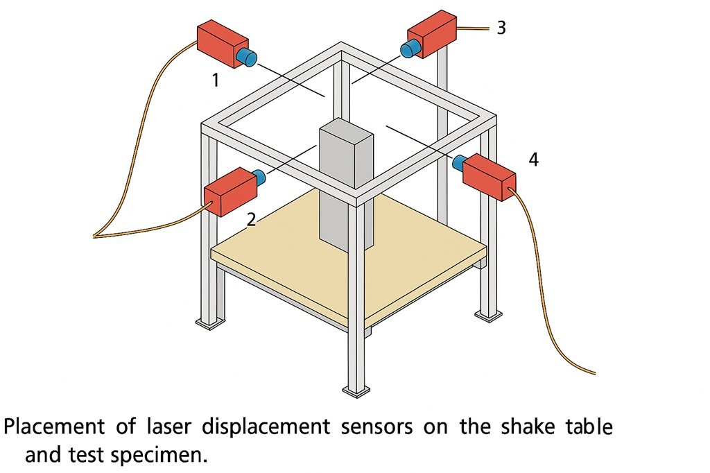
The experimental setup incorporated a suite of precision measurement instruments and sensors to monitor forces and displacements in real-time. The equipment configuration is summarized in Table 8. Two load cells were used to record vertical and horizontal forces, while six non-contact laser displacement sensors monitored dynamic movement at key structural points. All data were acquired using a StrainSmart® 8000 data acquisition system, enabling synchronized sampling.
| No. | Instrument | Type | Measurement Range |
| 1 | Vertical load cell | AEP transducers | 0–30 kN (compression) |
| 2 | Horizontal load cell | AEP transducers | 0–5 kN (tension/compression) |
| 3 | Laser sensors (×6) | MICRO-EPSILON ILD1302-200 | 0–200 mm, ±0.01 mm precision |
| 4 | DAQ System | StrainSmart® 8000 | — |
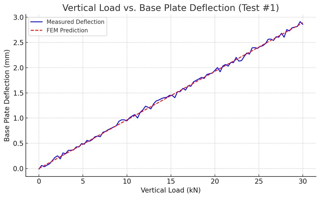
This test validated the table’s ability to apply a 30 kN vertical load to a specimen on the base plate. A ramp function was used to gradually apply the force, while the vertical deflection at the base plate’s center was recorded.
A maximum deflection of 2.87 mm was recorded–closely matching the FEM prediction of 2.89 mm. Minor fluctuations were attributed to sensor noise and micro-vibrations.
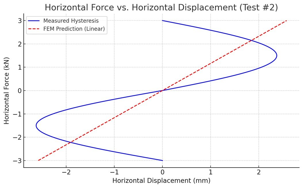
A lateral force of 3 kN was applied to the specimen via the base plate. Displacements of the top plate and upper frame were measured using the laser sensors.
The system showed slight hysteresis, due to friction in the guideways. Recorded displacements were 2.40 mm (top plate) and 2.04 mm (upper frame), slightly lower than FEM predictions (2.58 mm and 2.26 mm).
A sinusoidal ±200 mm motion was commanded via the control system. Displacement accuracy was measured using a calibrated laser sensor.
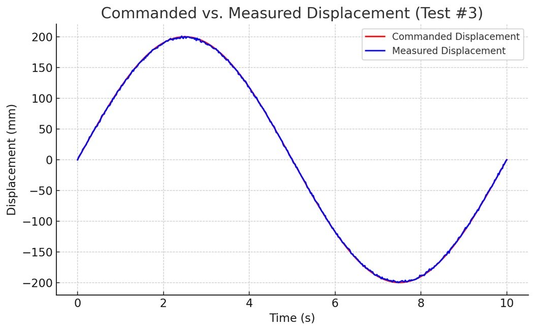
The deviation from the commanded path was only 0.45%, confirming high control fidelity.
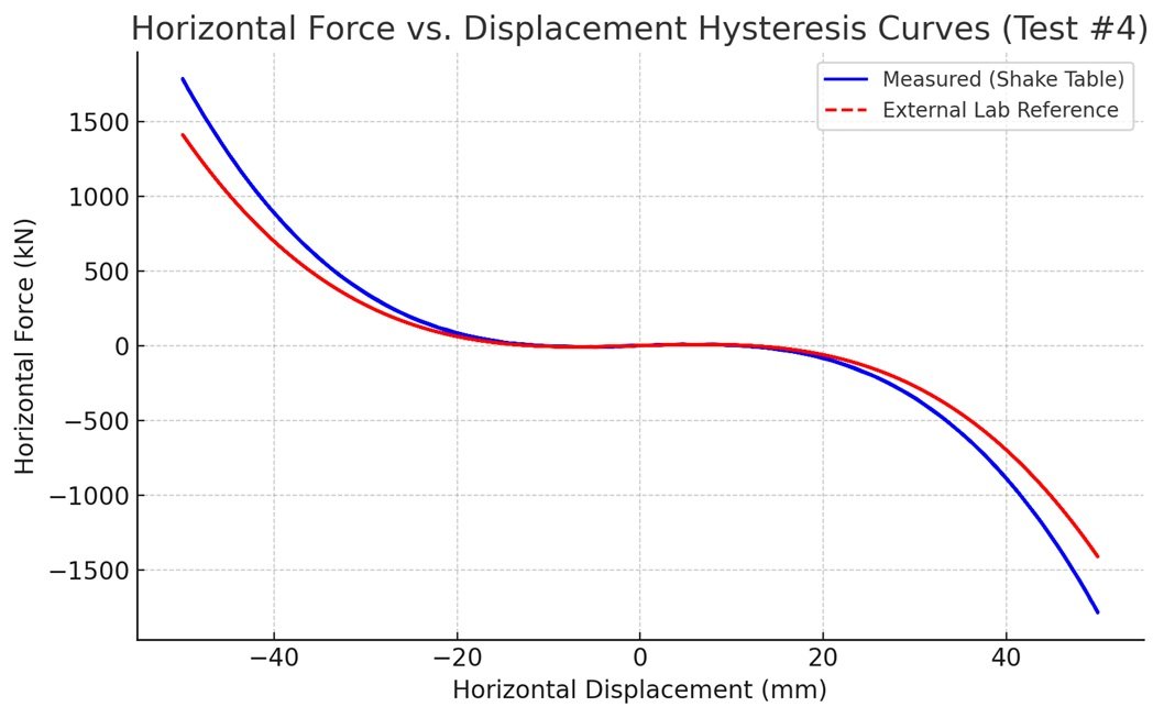
A final test assessed the shake table under cyclic conditions using a bioinspired sliding-stretching isolator (SSI). A preload of 25 kN was applied vertically, followed by a horizontal sinusoidal displacement (±50 mm at 0.4 Hz).
The experimental campaign confirmed the following:
These results confirm that the in-house-developed shake table is suitable for dynamic testing of mid-scale seismic isolation systems under realistic conditions.
This study presented the complete workflow for the design, modeling, construction, and validation of a laboratory-scale shake table specifically developed for the testing and experimental characterization of medium-scale seismic isolation devices, including innovative bioinspired prototypes. The main objectives were to build a cost-effective, high-performance system capable of delivering large lateral displacements, sustaining significant vertical loads, and executing programmable motion profiles with high precision.
A robust mechanical design strategy was implemented, based on modular aluminum framing, precision linear guideways, servo-controlled actuators, and custom top and base plates. The table was designed to deliver ±200 mm of horizontal displacement, vertical loads up to 30 kN, and peak horizontal velocities up to 1 m/s, making it suitable for a broad range of seismic simulation studies.
The system was simulated using a detailed finite element model, which confirmed that all components remain well within elastic stress limits under the target load conditions. The predicted deflections and stress distributions aligned with structural expectations, demonstrating that the table could reliably support the forces imposed during testing without compromising structural integrity.
A series of experimental validation tests were conducted to confirm the shake table’s functionality under real-world operating conditions. These tests validated:
The system demonstrated reliable performance, with minor discrepancies explained by frictional effects and measurement tolerances not considered in the numerical model. The close agreement between simulated and experimental data highlights the accuracy of both the design process and control implementation.
The developed shake table represents a flexible and scalable solution for research laboratories seeking to experimentally validate seismic isolation strategies, especially those involving non-conventional or sustainable designs. Its ability to support bioinspired, 3D-printed, or recycled-material-based isolators opens new opportunities for low-cost and environmentally conscious seismic protection systems.